Electronic symbols are used when drawing circuit diagrams to represent the basic components that make up the circuit. Engineers have to study these diagrams to understand how electronic devices work, the complicated collection of components that goes into them, and how they're connected together. Below, we'll be looking at some of the most frequently used electronic symbols that are found in circuit diagrams, manuals, and sometimes on equipment.
IEC 60617: Standard Graphic Symbols for Circuit Diagrams
The graphic symbols for electrical and electronic components are standardised, so that circuit diagrams can be read and recognised in many different countries. Since mass production of many devices has increased around the world, it's clear that the schematics for such devices must be uniform, so that all manufacturers are working to the same standards. It's also necessary to devise, standardise and introduce new symbols for the more advanced technology now in circulation.
Electronic Symbols
The symbols are mostly comprised of geometric lines and figures in different combinations. Specific meaning to individual symbols can be attributed by adding shading, a dot, an extra line, and numbers or letters.
Wires
There are various types of electronic wire or cabling used to conduct electrical current into and around an application. The symbols represent the wires, their connections, and types of cable.
Wires
This symbol shows any wire that conducts electrical current.
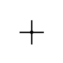
Connected Wires
This shows that two conductors are connected. Their junction point is represented by the Dot.
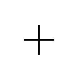
Unconnected Wires
This symbol without a Dot shows two unconnected wires or conductors.
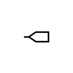
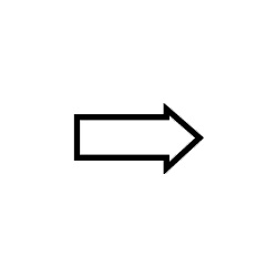
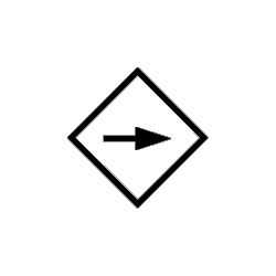
Input Bus Line
This depicts an input or incoming data bus.
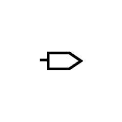
Output Bus Line
This depicts an output or outgoing data bus.
Bus Line
This symbol shows where several conductors join together to form a bus wire.
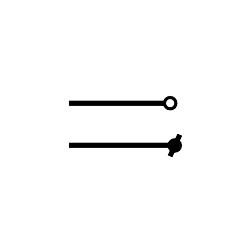
Terminal
The start or end point of a circuit.
Switches
An electronic switch is a device or component that can cause an electrical circuit to switch, either by diverting the current away from one conductor towards another or by interrupting it altogether. Such switches have two states, ON or OFF, so are categorised as binary devices.
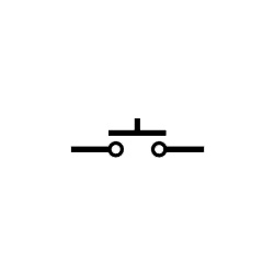
Push Button (Normally Open)
This shows a binary switch in the ON state. When the button is released it's in the OFF state.
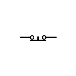
Push Button (Normally Closed)
This shows a binary switch in the OFF state. When the button is released it's in the ON state.
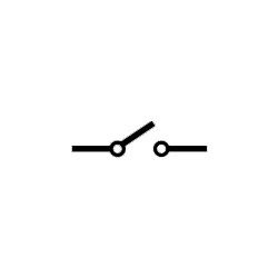
SPST Switch
This stands for Single Pole Single Throw and is a type of simple ON/OFF switch with only one input and one output.
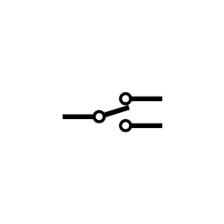
SPDT Switch
This stands for Single Pole Double Throw and is another type of ON/OFF switch. The single input current can be switched to either of two flow positions.
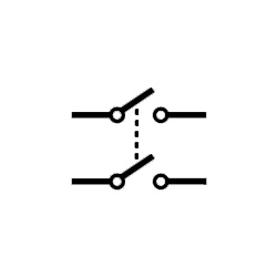
DPST Switch
Double Pole Single Throw switches have two inputs and two outputs, so can drive two circuits (throws) simultaneously.
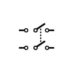
DPDT Switch
Double Pole Double Throw switches can change the flow position amongst four connected circuits.
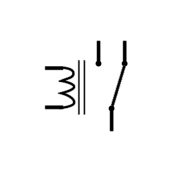
Relay Switch
Relay switches electronically control access to circuits.
Sources
These symbols are used to show the source of the power supplied to an electronic circuit.
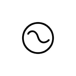
AC Supply
This depicts the circuit's AC power supply.
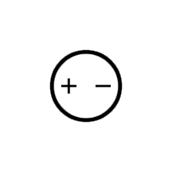
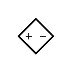
DC Supply
This depicts the circuit's DC power supply.
Constant Current Source
This symbol stands for the source of an independent constant current.
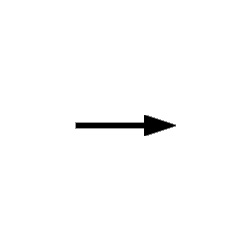
Controlled Current Source
This symbol stands for the source of a current dependent on another source (voltage or current).
Controlled Voltage Source
This symbol stands for the source of a voltage dependent on another source (current or voltage).
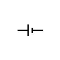
Single Cell Battery
This represents a single battery providing power to the circuit.
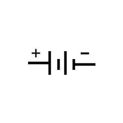
Multi-Cell Battery
This shows multiple single-cell batteries providing power, or one large cell battery.
Wave Generators
Wave generators are electrical or electronic circuits or devices designed to produce various types of waveform at any particular frequency.
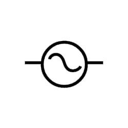
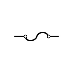
Sinusoidal Generator
This represents a generator of sine waves.
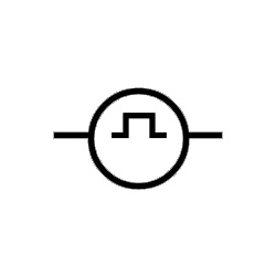
Pulse Generator
This represents a generator of pulse or square waves.
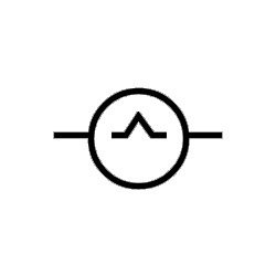
Triangular Wave
This represents a generator of triangular waves.
Ground
Earth, or ground, is the point where voltages are measured from in an electronic circuit, representing a direct physical connection of electricity to the earth.
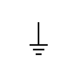
Ground
This symbol represents Ground, or perfectly conducting earth.
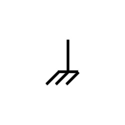
Signal Ground
This shows the point on a circuit from which a signal is measured. Several signal grounds may appear in a circuit where voltage drops occur.
Resistors
In electronic circuits, resistors provide a barrier device that can be used to divide voltages, reduce current flow, terminate transmission lines, adjust signal levels, bias active elements, and more.
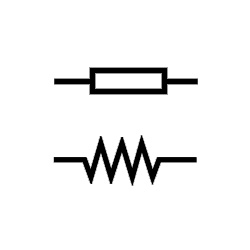
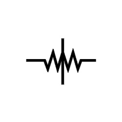
Resistor
These two symbols both represent a fixed resistor.
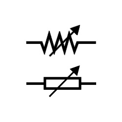
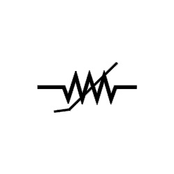
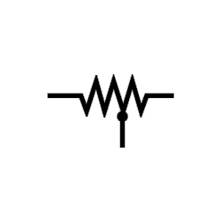
Rheostat
This depicts a two-terminal variable resistor, commonly used in a circuit to control the current.
Preset
This depicts a mini variable resistor with rotary control, also called a Trim Pot or Trimmer Resistor, for light or heat circuits.
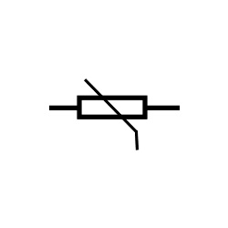
Thermistor
This shows a temperature-sensitive resistor.
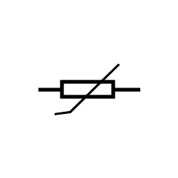
Varistor
This shows a Voltage Dependent Resistor used to protect circuits from voltage surges and fluctuations.
Capacitors
These are simple electrical components that can store an electrical charge. They usually comprise a layer of insulation sandwiched between two layers of conducting material.
Magneto
This depicts a Magneto or Magnetic Dependent Resistor (MDR).
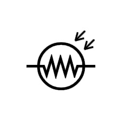
LDR
This symbol is for Light Dependent or Photo Resistors.
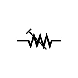
Tapped
This shows a fixed resistor of wound wire with one or more intermediary terminals. Tapped resistors are common in voltage divider applications.
Attenuator
This shows a device that attenuates or reduces signal power.

Memristor
This symbol shows a resistor that varies its resistance according to the charge flow direction.
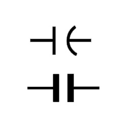
Non-Polarised Capacitor
Both these symbols represent non-polarised capacitors, which store a charge as electrical energy. They are found in both DC and AC circuits.
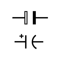
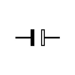
Polarised Capacitor
These two symbols both show polarised capacitors, used in DC circuits as filters, passing or bypassing low-frequency signals.
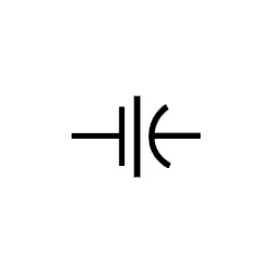
Electrolytic Capacitor
This symbol represents capacitors with an oxide-coated plate to increase their capacitance. Usually polarised and common in DC circuits.
Feed Through Capacitor
This symbol shows a capacitor with low impedance path to the circuit's ground. Commonly used for high-frequency signals.
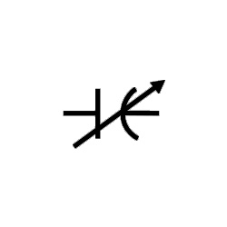
Variable Capacitor
This shows a variable capacitor, which can be adjusted with a knob.
Inductors
Inductors are usually made up of a coil of insulated wire. They can store energy within a magnetic field when electric current is passed through them. Inductors are also called coils, reactors or chokes.
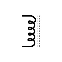
Iron Core Inductor
This represents a type of inductor with an iron core rather than ferrite, as iron is less permeable.
Ferrite Core Inductor
This represents a type of inductor used to suppress electromagnetic wave interference.
Centre Tapped Inductor
This shows an inductor used in signal coupling.
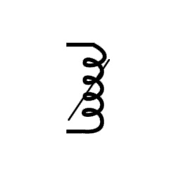
Variable Iron Core
This shows a variable inductor, which can slide its magnetic core in or out of its coil. Often used instead of ferrite core inductors.
Diodes
Diodes are electronic components with two terminals that conduct electrical current in one direction. In one direction they offer low resistance, while providing high resistance in the opposite.
PN Junction Diode
This represents a diode that enables current flow in forward bias condition only.
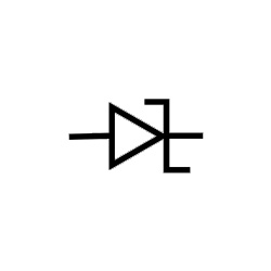
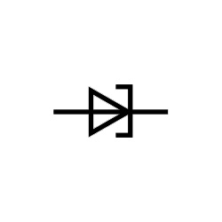
Zener Diode
This shows a diode that can enable current flow in forward and reverse bias condition to regulate voltage.
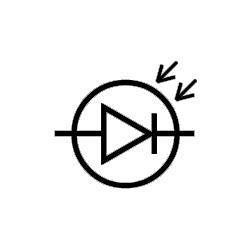
Photodiode
This depicts a light detecting diode that converts the energy into voltage or current using a photoelectric effect.

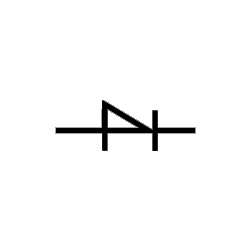
Varactor Diode
This shows a varactor diode, or variable capacitance (varicap) diode. Its capacitance varies according to the input voltage.
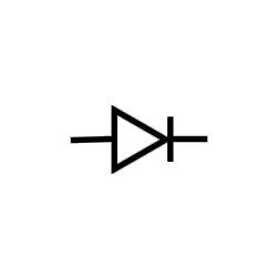
Shockley Diode
This depicts a four-layer diode for fast switching operations.
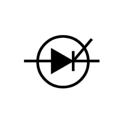
Schottky Diode
This represents a diode used for rapid switching with low forward voltage drop.
Tunnel Diode or Esaki Diode
This shows a fast switching diode which is good for microwave frequencies.
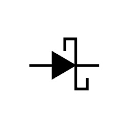
Thyristor
This shows a four-layered diode with alternating P and N layers acting as bistable switches.
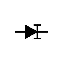
Constant Current Diode
This depicts a diode that can limit current to a preset maximum value. Also called Current Regulating or Limiting Diode.
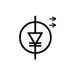
Laser Diode
This depicts a semiconductor device, like a light-emitting diode.
Transistors
Transistors are the foundation of modern electronics. These semiconductor devices can switch or amplify electrical power and electronic signals.
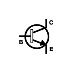
NPN
This shows a combination transistor, with a P-type semiconductor laid between two layers of N-type semiconductors. ON with forward bias.
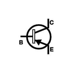
PNP
This shows a combination transistor, with an N-type semiconductor laid between two layers of P-type semiconductors. ON with reverse bias.
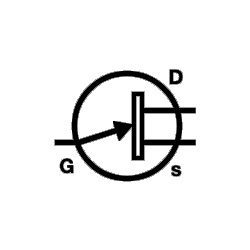
N-Channel JFET
This shows an N-Channel JFET transistor made with N-type silicon bars forming two lateral PN junctions.
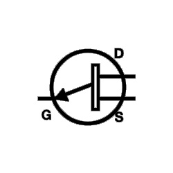
P-Channel JFET
This shows a P-Channel JFET transistor made with P-type silicon bars which forms two lateral PN junctions.
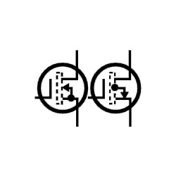
Enhancement MOSFET
This shows a positive gate-operated MOSFET transistor, which enhances channel conductivity.
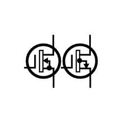
Depletion MOSFET
This shows a negative gate-operated MOSFET transistor, which decreases channel conductivity.
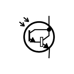
Photo Darlington
This shows a similar phototransistor, but with much higher gain and sensitivity.
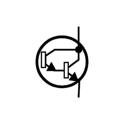
Darlington Transistor
This depicts a phototransistor with high current gain.
Logic Gates
Logic gates provide the foundations of a digital system. These electronic circuits have only one output, but can have one or more inputs. How the gate functions is based on the interaction of the input and the output (AND, OR or NOT), according to a form of logic known as Boolean Logic.
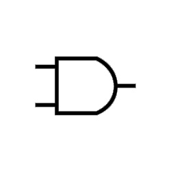
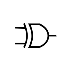
AND Gate
This symbol shows the basic conjunct gate. The AND gate output in an electronic circuit will be high only if all its inputs are high.
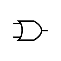
OR Gate
This symbol shows a disjunct gate. The OR gate output will be high when one or more of its inputs are high.
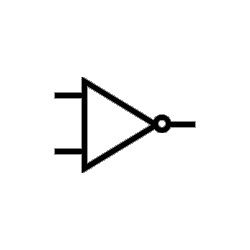
NOT Gate
This represents an inverter, where the gate inverts the input to produce the output.
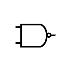
NAND Gate
This symbol shows a NOT-AND gate. The outputs of this gate will be high when all its inputs are low.
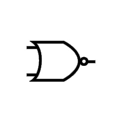
NOR Gate
This represents a NOT-OR gate. All the outputs of this gate will be high if one or more of its inputs are low.
EXOR
This symbol shows an Exclusive OR gate. The output of this gate will be high when either, but not both inputs are high.
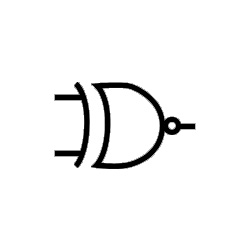
EXNOR
This represents a NOT-EXOR gate. The output of this gate will be high when both inputs are the same (either high or low).
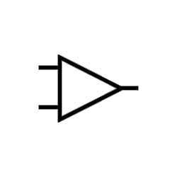
Buffer
This shows a digital buffer, which can isolate the input in an electronic circuit from the output.
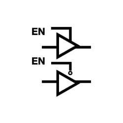
Tri-State Buffer
This shows a logic inverter with three possible outputs directed by a control signal.
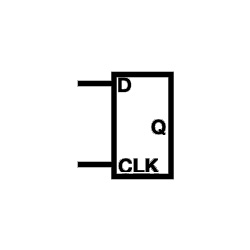
Flip Flop
This symbol shows a single-bit memory device, or latch, with two states, either 1 or 0.
Amplifier
These electronic devices are used to increase or amplify an electrical or electronic signal.
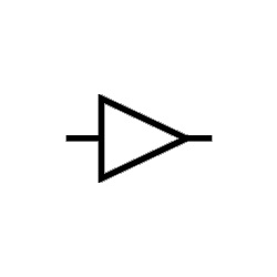
Basic Amplifier
This represents a device that increases the power of a small input signal.
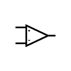
Operational Amplifier
This represents a voltage amplifier with differential input and very high gain.
Antennae
Antennae are composed of metal transducers that can intercept and convert electromagnetic voltages into radio waves, or vice versa.
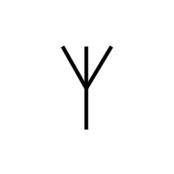
Antenna
This symbol is for a simple antenna, which converts electrical energy into radio waves.
Loop Antenna
This symbol is for an antenna shaped in a loop, for low frequency ranges.

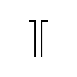
Dipole Antenna
This symbol shows the most common type of antenna, such as those on older TV sets or short wave transmitters.
Transformers
These passive electrical components are the method by which electrical energy can be transferred between electrical circuits.
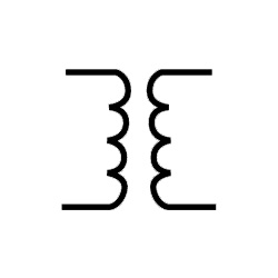
Transformer
This shows a basic component that uses electromagnetic induction to transfer energy from one circuit to one or more other circuits, usually to change the AC current voltage.
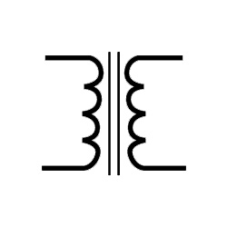
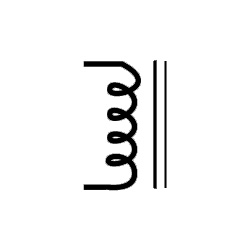
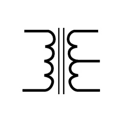
Iron Core Transformer
This represents a transformer with a core of magnetic material which can confine a magnetic field.
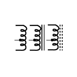
Centre Tapped Transformer
This represents a type of transformer used in rectifier circuits. Its secondary windings are divided into two equal parts, producing two individual output voltages.
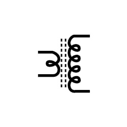
Step Up Transformer
This represents a transformer commonly used in inverters. It has more turns in its secondary winding than in its primary winding, producing higher output than input voltage.
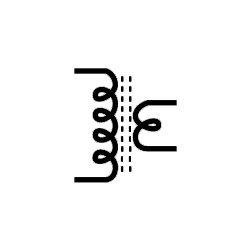
Step Down Transformer
This represents a transformer with fewer turns in its secondary winding than in its primary winding, producing lower output than input voltage.
Sound Devices
These symbols are used for any devices in an electronic circuit that make a noise when activated.
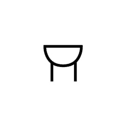
Buzzer
This represents a device that buzzes when voltage is applied.
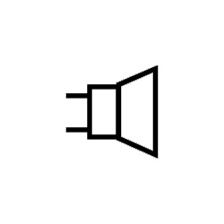
Loudspeaker
This represents a device that converts an electrical signal into a sound signal.
Converters
Converters are devices that convert the type of signals used in electronic circuits (analogue to digital and vice versa).
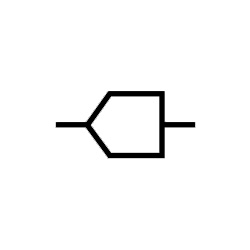
ADC
This shows a converter that changes analogue signals (usually voltage) into digital code.
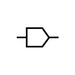
DAC
This shows a converter that changes digital code into analogue signals.
Lighting
Light Bulb
Lights are sometimes incorporated into an electronic circuit with this symbol.
Miscellaneous
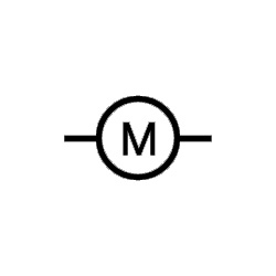
Motor
This symbol shows an electric motor that produces mechanical energy.
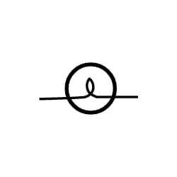
Fuse
This symbol represents a fuse.
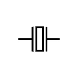
Crystal Oscillator
This represents a device that can generate an electrical signal with very precise frequency.