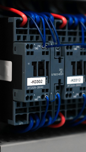
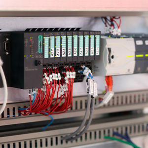
Contactors are used for all kinds of electrical and automated applications, including the control of lighting, heating and electric motors. Common coil voltages are 24V AC and DC coil, and 110V and 230V AC coil options, with many different amp and wattage levels within each individual category. An example of a contactor is a 24V electromagnetic coil used to control a 230V motor switch circuit.

What Are Contactors?
A contactor is an electrically controlled switch similar to a relay, and is basically a low voltage circuit component used for switching a higher-current electrical power circuit (more than 15 amps or a few kw). It can be connected directly to devices with a high load, as it has rapid open and closing features designed to control and suppress the electrical arc discharged when a heavy motor current is interrupted. It is not, however, designed as a circuit breaker to interrupt a short circuit current.
Contactors come in a wide variety of forms, with capacities ranging from a minimal breaking current load to a very high amperage and voltage. Sizes range from a few millimetres to more than a metre across, with an assortment of features according to their function. Almost all standard contactors are fitted with several form A or 'normally open' contacts, and some contactors have optional low-current auxiliary contacts, for independent functions such as pilot lights.
How Do Contactors Work?
A contactor is made up of three components: the enclosure, the electromagnet or coil, and the contacts (sometimes also called poles). The enclosure is self-explanatory and houses the coil and the contacts, including any auxiliary contacts. It is made of any insulating material such as a thermosetting plastic which will insulate and protect the contacts. It helps to prevent people touching the contacts and may also protect against environmental contamination by oil, dust, weather, etc. The coil or electromagnet provides the driving force which closes the contacts, and consists of a static core and a moving core. The contacts are the current-carrying components and can include power and auxiliary contacts and contact springs.
When a current is passed through the coil, it produces a magnetic field that attracts the contactor's moving core. This moving core propels the moving contact by electromagnetic force towards the fixed contacts and holds them closed together. When power to the coil is turned off, the moving core is returned to its initial position, either by a contact spring or by gravity, and the contacts reopen.
How To Select a Contactor
Because the range of available contactors is so vast, it is important to select the correct type and size of contactor for the specific task you need it to do. This can be as simple as turning a non-inductive heater on and off, or as complex as the switching of highly inductive loads such as series and shunt motors. The range of contactors is rated accordingly, starting at AC-1 for the simplest heater and expanding in load-bearing capacity up to DC-23 for series motors, and includes such tasks as the switching of resistive and inductive motor loads and the control of solid state and electromagnetic loads.
The International Electrotechnical Commission (IEC) is responsible for setting international standards for all kinds of electrical and technical components, and publishes a list of applicable contactor types.
Selecting a contactor relies on correctly identifying three key elements, starting with the contacts:
- the applicable IEC utilisation category (or a comprehensive duty description)
- how many normally open (NO) or normally closed (NC) contacts there are
- what the switching input current is in amperes or the power rating
- what and how much voltage is used, whether AC or DC, 24V, 230V, etc
- how many auxiliary NO or NC contacts there are, including any time-delayed contacts. Auxiliary contacts may have a different power rating from the main contacts.
The coil should be identified for:
- AC or DC operation
- control circuit voltage, 24V AC or DC, 230V AC, etc. DC voltage supply may require lower power, while AC needs to be on the correct supply frequency
Further considerations to take into account include:
- what environment it will be used in (interior/exterior, etc)
- what the ambient temperature will be
- whether it is a modular or stand-alone design
- whether any additional ancillary components are required, such as busbars, thermal overload relays, mechanical interlocks or motor protection circuit breakers
How to Wire a Contactor
Once the contacts and coil have been correctly rated, the contactor can be wired up. Study the manufacturer's information in order to identify the two input pins and the two or more output pins, which should be shown as NO or NC. If there is an auxiliary contact, make sure it is wired with the correctly rated current.
Remove all the wires from any live current before running them to the input and output points on the contactor. All wires should be printed with the power rating on the external casing, and should be cut to the correct length to reach the relevant contacts.
The outer casing should be stripped back for approximately half an inch (13mm) to expose the naked wire, which may consist of several strands. These strands should be checked for any stray strands, ensuring that no stray strand is left out which might make accidental contact with another part of the equipment.
Use a screwdriver to loosen the screws in the contacts holding block, and carefully insert the input wires into the block, up to the cut edge of the casing. Make sure no loose strands are left out which could cause damage through unintended contact. Once the input wires are inserted into the contacts, carefully tighten the holding screws.
Test that the contacts are working by turning on the input voltage. Listen carefully for the click that should occur when the contactor is engaged.
Turn off the input power and insert the output wires into the contacts in the same manner, making sure no stray strands are left out of the contact block. Tighten up the holding screws.


